A tour of some XLS/xlsynth codegen options
This is a brief tour of some options for generating pipelines from the “Accelerated Hardware Synthesis” (XLS) project. Namely, whether to flop inputs/outputs or to alternatively allow “combinational overhang” for the module you’re generating, i.e. whether to assume you can expose significant "input-to-register" (I2R) or "register-to-output" (R2O) delay time.
🗒️ Aside: There are some additional tools and capabilities, particularly around Rust, that are available under the name “xlsynth”. You can basically think of XLS and xlsynth as the same umbrella project/stuff.
Functionality from the XLS toolchain is integrated into a binary called the xlsynth-driver which you can install via cargo:
cargo install xlsynth-driver --version 0.0.169
Once you have the xlsynth-driver you can quickly get going generating Verilog pipelines — consider the following (contrived) example:
echo 'fn f(x: u32, y: u32, z: u32) -> u32 { x * y + z }' > /tmp/sample.x
With this .x file available we run:
xlsynth-driver dslx2pipeline \
  --dslx_input_file /tmp/sample.x --dslx_top f \
  --delay_model asap7 --pipeline_stages 2 --module_name f \
  > /tmp/f_no_io_flops.sv
This produces a Verilog module as text for us in our standard output:
module f(
  input wire clk,
  input wire [31:0] x,
  input wire [31:0] y,
  input wire [31:0] z,
  output wire [31:0] out
);
  // lint_off MULTIPLY
  function automatic [31:0] umul32b_32b_x_32b (input reg [31:0] lhs, input reg [31:0] rhs);
    begin
      umul32b_32b_x_32b = lhs * rhs;
    end
  endfunction
  // lint_on MULTIPLY

  // ===== Pipe stage 0:
  wire [31:0] p0_umul_8_comb;
  assign p0_umul_8_comb = umul32b_32b_x_32b(x, y);

  // Registers for pipe stage 0:
  reg [31:0] p0_z;
  reg [31:0] p0_umul_8;
  always @ (posedge clk) begin
    p0_z <= z;
    p0_umul_8 <= p0_umul_8_comb;
  end

  // ===== Pipe stage 1:
  wire [31:0] p1_add_14_comb;
  assign p1_add_14_comb = p0_umul_8 + p0_z;
  assign out = p1_add_14_comb;
endmodule
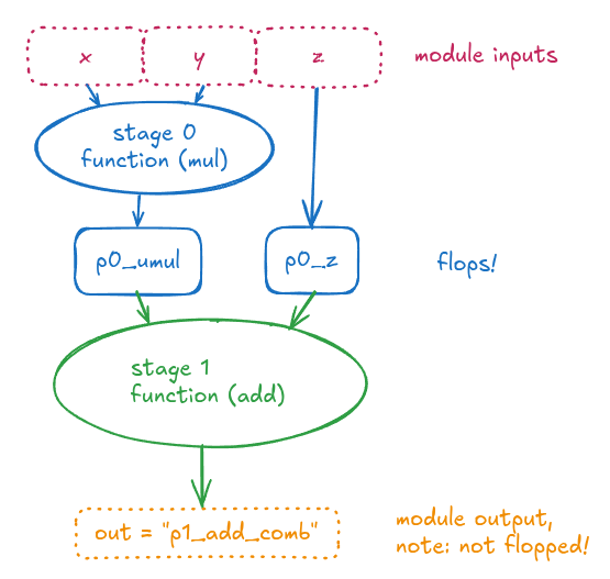
If you look at how this Verilog is structured, the multiply is scheduled into pipeline stage 0, and the addition is scheduled into pipeline stage 1. That seems to make sense: we had two operations and requested 2 pipeline stages, so it split them into two pieces of combo logic, and put flops in between.
https://excalidraw.com/#json=VmPMNwXtuMyAYSQ57J4KD,SSocJ0O_dd9MKK74CZYpPA
It is notable, however, that the multiply operation (blue circle) is creating a “combinational overhang” on input, i.e. there is a combinational logic cloud (via the multiply operation) that the inputs x and y pass through immediately after entering this module. These are also typically seen as “input to register” (or “register to output”, for the green circle) delays in a timing report.
The implication of this is that the instantiating module has to be aware of how much of a clock cycle that “combinational overhang” is going to require, because the instantiator needs to make sure there is that much slack available in the clock cycle for the inputs it feeds as x and y , in order to close timing.
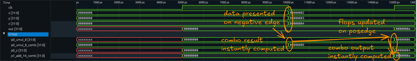
To invoke this pipeline we expect the final result to show up one clock cycle after we present the input:
- on the cycle we present the input: it goes through the blue combinational cloud and gets flopped into the blue flops
- on the next cycle: the flopped values flow through the green combinational cloud and get presented as output.
🗒️ Aside: because we’re running in simulation without any kind of timing analysis we traverse through the combinational clouds instantaneously. We present the input on the negative edge of a cycle, so the blue cloud is (trivially) completed by the time the posedge of the clock arrives to flop the data into the blue flops, and once the data is flopped in on the next cycle we (instantaneously) have completed the combinational computation through the green combinational cloud, so the data is available to sample from the output.
We can observe this with the xlsynth-driver command that executes our Verilog pipeline:
$ xlsynth-driver run-verilog-pipeline /tmp/f_no_io_flops.sv \
    --latency 1 "(bits[32]:2, bits[32]:3, bits[32]:4)" \
    --waves /tmp/dump.vcd
Using provided input: (bits[32]:2, bits[32]:3, bits[32]:4)
out: bits[32]:10
And then observing the waves:
$ surfer /tmp/dump.vcd
We see:
https://excalidraw.com/#json=l47Sza__TzOgr1v4qS4-q,e7oetd8I3n8c2eCnrLZQdQ
Using I/O flops to increase abstraction
A practice folks often try to make a “nicer / less leaky abstraction” is to terminate inputs with flops immediately, which alleviates the instantiator from needing to think about how much of a clock cycle will be taken up by the instantiating module, and allows the instantiating module to know it has a whole clock cycle to fit within for its first cycle.
To enable this, the xlsynth-driver has additional options we can set:
$ xlsynth-driver dslx2pipeline --help
Converts DSLX to SystemVerilog

Usage: xlsynth-driver dslx2pipeline [OPTIONS] --delay_model <DELAY_MODEL> --dslx_input_file <DSLX_INPUT_FILE> --dslx_top <DSLX_TOP>

Options:
[snip]
      --flop_inputs <BOOL>
          Whether to flop input ports (vs leaving combinational delay into the I/Os) [possible values: true, false]
      --flop_outputs <BOOL>
          Whether to flop output ports (vs leaving combinational delay into the I/Os) [possible values: true, false]
[snip]
By setting these options we will create a pipeline with a full “flop sandwich” on the outside of it; i.e. flops that immediately latch the input, and flops that immediately launch into the output.
$ xlsynth-driver dslx2pipeline --dslx_input_file /tmp/sample.x --dslx_top f \
    --delay_model asap7 --pipeline_stages 2 --module_name f \
    --flop_inputs true --flop_outputs true > /tmp/f_io_flops.sv
Which produces:
module f(
  input wire clk,
  input wire [31:0] x,
  input wire [31:0] y,
  input wire [31:0] z,
  output wire [31:0] out
);
  // lint_off MULTIPLY
  function automatic [31:0] umul32b_32b_x_32b (input reg [31:0] lhs, input reg [31:0] rhs);
    begin
      umul32b_32b_x_32b = lhs * rhs;
    end
  endfunction
  // lint_on MULTIPLY

  // ===== Pipe stage 0:

  // Registers for pipe stage 0:
  reg [31:0] p0_x;
  reg [31:0] p0_y;
  reg [31:0] p0_z;
  always @ (posedge clk) begin
    p0_x <= x;
    p0_y <= y;
    p0_z <= z;
  end

  // ===== Pipe stage 1:
  wire [31:0] p1_umul_15_comb;
  assign p1_umul_15_comb = umul32b_32b_x_32b(p0_x, p0_y);

  // Registers for pipe stage 1:
  reg [31:0] p1_z;
  reg [31:0] p1_umul_15;
  always @ (posedge clk) begin
    p1_z <= p0_z;
    p1_umul_15 <= p1_umul_15_comb;
  end

  // ===== Pipe stage 2:
  wire [31:0] p2_add_20_comb;
  assign p2_add_20_comb = p1_umul_15 + p1_z;

  // Registers for pipe stage 2:
  reg [31:0] p2_add_20;
  always @ (posedge clk) begin
    p2_add_20 <= p2_add_20_comb;
  end
  assign out = p2_add_20;
endmodule
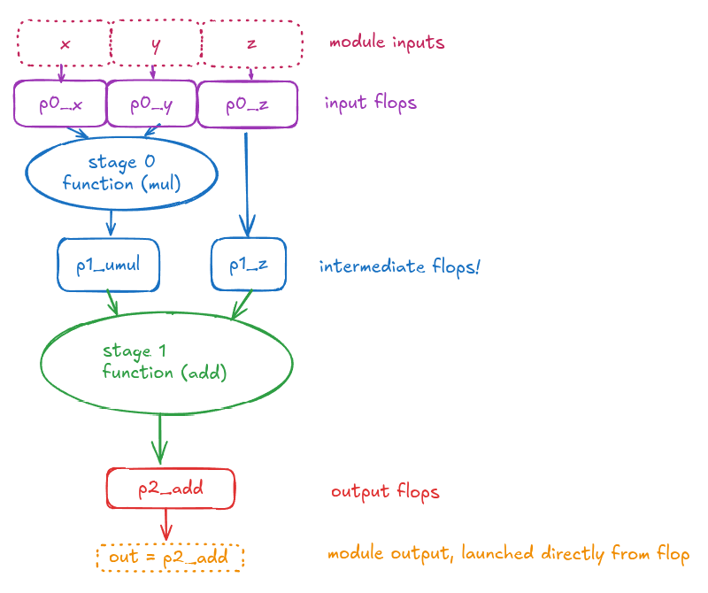
In this module you can see that x, y , and z are immediately terminated in a register, and the output is immediately driven (via assign) from a flop.
https://excalidraw.com/#json=Buxb5w5OZtAz41sizhocw,RrJZ0kP3eF97Qj7CGpeT1g
It seems worth pointing out that each “layer” of flops has its own pX_ prefix, so when we add input/output flops we go from the single layer of p0_* intermediate flops in the first diagram to three layers, p0_*, p1_*, and p2_* in the second diagram. We still fundamentally split the pipeline into two pieces in the same way, but we terminated signals on input/output differently.
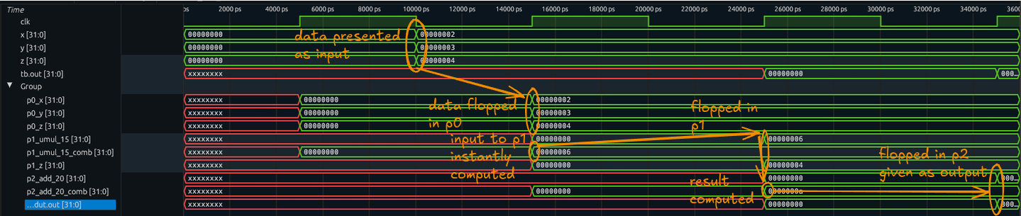
Now we can run the pipeline with a latency of 3 clocks:
$ xlsynth-driver run-verilog-pipeline /tmp/f_io_flops.sv \
    --latency 3 \
    "(bits[32]:2, bits[32]:3, bits[32]:4)" \
    --waves /tmp/dump.vcd
Using provided input: (bits[32]:2, bits[32]:3, bits[32]:4)
out: bits[32]:10
Which shows us the following waveform:
https://excalidraw.com/#json=D4XjKS--YzvLMc0AoSplr,ArZlum0fl1H6Oxuqx2L_yQ
“Valid” Signaling Options For Clock Gating
XLS also supports “valid” signals being offered to/from the pipeline. This allows you to indicate on which clock cycles you’re feeding legitimate into the pipeline, and that indication rides a “conveyor belt” through the pipeline stages which can then appear at the output as an “output valid” indicator next to the corresponding data result.
This valid signaling is typically used to guard the update of the flip flops in the pipeline, which leads to clock gating, where we select a flip-flop cell that has an enable signal that indicates whether the flip flop actually needs to capture the input value, or can just retain its previous state/value. In modern digital logic design this is common to do pervasively in order to avoid expending extra power for “useless” work on clock cycles where the data is irrelevant.
XLS supports valid signaling via the following flags:
$ xlsynth-driver dslx2pipeline \
   --dslx_input_file /tmp/sample.x --dslx_top f \
   --delay_model asap7 --pipeline_stages 2 --module_name f \
    --flop_inputs true --flop_outputs true \
    --input_valid_signal=in_valid --output_valid_signal=out_valid \
    --reset=rst > /tmp/f_io_flops_with_valid.sv
Note the addition of input_valid_signal and output_valid_signal — now our generated pipeline looks like the following:
module f(
  input wire clk,
  input wire rst,
  input wire in_valid,
  input wire [31:0] x,
  input wire [31:0] y,
  input wire [31:0] z,
  output wire out_valid,
  output wire [31:0] out
);
  // lint_off MULTIPLY
  function automatic [31:0] umul32b_32b_x_32b (input reg [31:0] lhs, input reg [31:0] rhs);
    begin
      umul32b_32b_x_32b = lhs * rhs;
    end
  endfunction
  // lint_on MULTIPLY

  // ===== Pipe stage 0:
  wire p0_load_en_comb;
  assign p0_load_en_comb = in_valid | rst;

  // Registers for pipe stage 0:
  reg p0_valid;
  reg [31:0] p0_x;
  reg [31:0] p0_y;
  reg [31:0] p0_z;
  always @ (posedge clk) begin
    p0_x <= p0_load_en_comb ? x : p0_x;
    p0_y <= p0_load_en_comb ? y : p0_y;
    p0_z <= p0_load_en_comb ? z : p0_z;
  end
  always @ (posedge clk) begin
    if (rst) begin
      p0_valid <= 1'h0;
    end else begin
      p0_valid <= in_valid;
    end
  end

  // ===== Pipe stage 1:
  wire p1_load_en_comb;
  wire [31:0] p1_umul_16_comb;
  assign p1_load_en_comb = p0_valid | rst;
  assign p1_umul_16_comb = umul32b_32b_x_32b(p0_x, p0_y);

  // Registers for pipe stage 1:
  reg p1_valid;
  reg [31:0] p1_z;
  reg [31:0] p1_umul_16;
  always @ (posedge clk) begin
    p1_z <= p1_load_en_comb ? p0_z : p1_z;
    p1_umul_16 <= p1_load_en_comb ? p1_umul_16_comb : p1_umul_16;
  end
  always @ (posedge clk) begin
    if (rst) begin
      p1_valid <= 1'h0;
    end else begin
      p1_valid <= p0_valid;
    end
  end

  // ===== Pipe stage 2:
  wire [31:0] p2_add_21_comb;
  wire p2_load_en_comb;
  assign p2_add_21_comb = p1_umul_16 + p1_z;
  assign p2_load_en_comb = p1_valid | rst;

  // Registers for pipe stage 2:
  reg p2_valid;
  reg [31:0] p2_add_21;
  always @ (posedge clk) begin
    p2_add_21 <= p2_load_en_comb ? p2_add_21_comb : p2_add_21;
  end
  always @ (posedge clk) begin
    if (rst) begin
      p2_valid <= 1'h0;
    end else begin
      p2_valid <= p1_valid;
    end
  end
  assign out_valid = p2_valid;
  assign out = p2_add_21;
endmodule
The primary difference you’ll observe is that we now have these load_en (load enable) signals that guard the update of the flip-flops in the design.
Now that we have the “output valid” signal we don’t need to specify the latency to know when the result from the pipeline has come available:
$ xlsynth-driver run-verilog-pipeline \
    /tmp/f_io_flops_with_valid.sv \
    "(bits[32]:2, bits[32]:3, bits[32]:4)" \
    --waves /tmp/dump.vcd \
    --input_valid_signal=in_valid \
    --output_valid_signal=out_valid \
    --reset=rst
Using provided input: (bits[32]:2, bits[32]:3, bits[32]:4)
out: bits[32]:10
This produces a waveform where we see a “pulse” where the inputs go valid and the corresponding output is presented as valid:
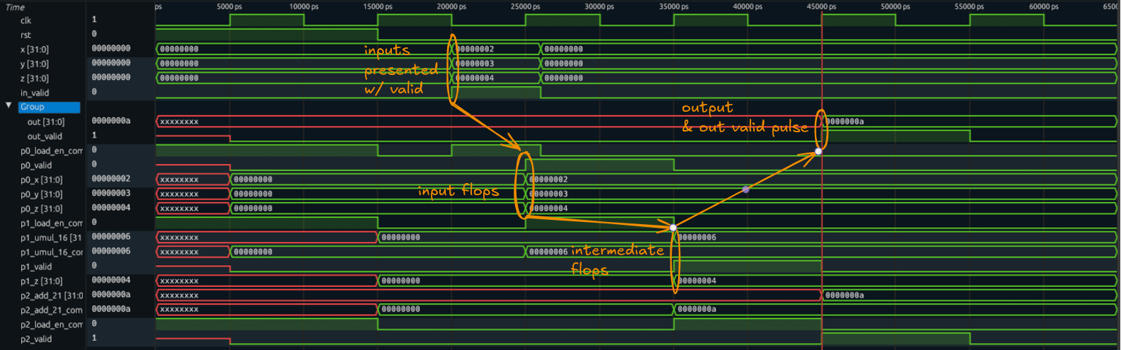
https://excalidraw.com/#json=960UwNKx3UGqQx68b77TZ,Ktf3T9ZTLCnaD4XpsnoxGg
When do users reach for these options?
We noted that putting flops on input/output make a cleaner timing interface, so that instantiators don’t need to worry about how much of the clock cycle is consumed. So when do people opt to remove the input/output flops in practice? The answer is, sometimes people want to control more precisely how XLS pipelines are integrated into the broader design.
For example, imagine you had two XLS pipelines that both produced a 32-bit output value, and you wanted to mux those together and flop them, and you wanted to write that instantiate/mux/flop integration in Verilog. To do that you would probably not want to dedicate a whole pipeline stage to muxing the two pipeline results together, you’d want to drop the output flops and assume that your 2:1 mux will fix in the remaining picoseconds of the clock cycle that were not used by the “combinational overhang” on output from the XLS modules.
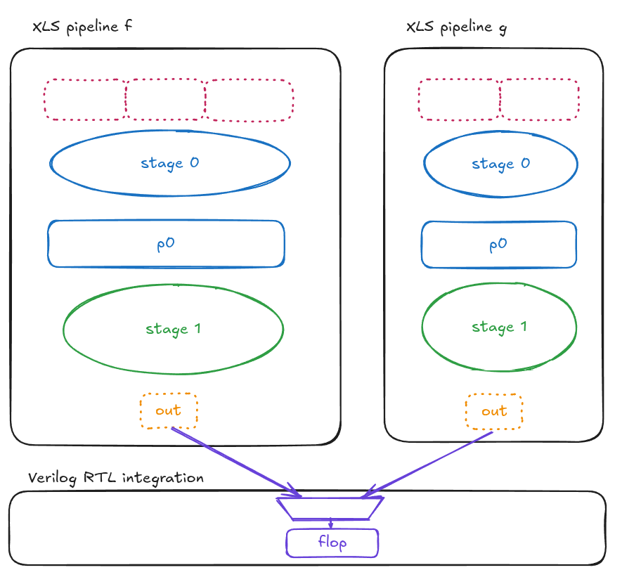
https://excalidraw.com/#json=Wp-8h0symSxC9WvtPl-X-,9gsPPN58XOB7_-MM04VHuA
Why are we still thinking about people writing Verilog, why doesn’t XLS methodology “take over” everything?
This gets into the “soul of XLS” as a “Mid Level Synthesis” tool. XLS intends to be a swiss army knife that lets you use it at all different levels of abstraction and control. It wants for you to always know what you’re getting as a result and why.
Case in point, if you want power to specify your exact control signaling outside of some XLS specified code block, XLS wants to let you do that. It emits output metadata about module signatures and timings that enable automatic integration and verification of timing properties for the resulting module.
If, on the other hand, you did want to hand your whole ALU over to XLS, it wants that to be possible too — but it doesn’t want to preclude the version where you have more control to make individual components in XLS and stitch them in whatever way you choose. Our tag line is that XLS can be used as “always blocks on steroids”, where you can see what you’re going to get out and why, and have control and knobs that govern exactly how that output artifact is generated.
What I think of as “classic HLS” had this conceptual usage trap, where the flows encouraged you to feel pretty “all in” on the pervasive HLS methodology and it tended to be somewhat opinionated in that regard — you couldn’t as easily mix and match some things that were best done in higher level, portable, re-targetable and re-usable code with other things where you wanted all of the control and to really write at the RTL cycle by cycle level of abstraction.
There are even ways to write XLS at a cycle-by-cycle level of abstraction, akin to RTL, but it doesn’t force you to do that if you’d rather do integration in your existing HDL environment/flow.
XLS embraces the “libraries, not frameworks” philosophy that we’re familiar with from software engineering, but in this case for component-level design of reusable, re-targetable, and flexibly-instantiable hardware modules, where users can make their own integration choices and leverage the layer(s) of abstraction that naturally provide them value.